Installation of Medium Kits
Here we'll address the installation of Medium Kits (also the sub-categories Eco, Premium, and Classic), and of related self-assembled cable trellis systems. The Medium Classic does have some exceptions, for which you can find details in the first diagram. All information on this page should be supplemented by the 10 - 25 installation diagrams for the respective cable system. Please follow that link and go to the cable system you have ordered. The diagrams you will find there complete the installation steps on this page. And before ordering, please also check to see if you need tools!
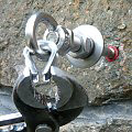
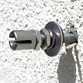
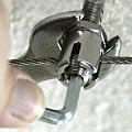
Did you order a Medium Classic cable system? Then there may be an exception to usual installation: if your Classic system contains eyebolts (photo) in addition to cable mounts, please jump to the special case 1. If it contains only eybolts, (like system 6010 Classic), then go to special case 2. In all other cases-- including Eco and Premium-- continue reading on this page.
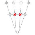
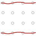
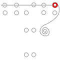
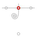
The symbols in the diagram represent the rope mounts; the red bars indicate the alignment of the grooves of the head. After drilling, clean all holes with a hole brush and/or blower and then attach the cable mounts (photo), preferably without grub screws. For this step, please refer to the respective product sheet for each mount (the standard mounts for Medium construction styles: Eco Medium Kits-- WH 08111, Classic Medium Kits-- mostly WH 10151, and with Premium Medium Kits-- WM 08133).
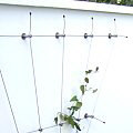
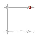
The first step will be to cut the cable segments to the desired length (including an additional 30 cm overhang to that measurement). Place the cables loosely in the grooves of the mounts (photo) without tightening the grub screws. The cable ends should protrude on both sides by at least 10 cm. The diagrams on the page of your kit will help you with the steps for installation; untensioned (slack) cables are symbolized by a wavy shape.
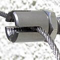
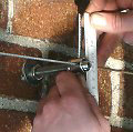
For each trellis kit, the cables can be mounted in several ways.The diagrams of the basic form show an installation requiring as little cable cutting as possible and one in which a turnbuckle (wire rope tensioner) is not required. The wire rope is initially laid slack in the first mount, with about 10 cm overhang. The grub screw is then inserted and moderately tightened. In the second step, grip the mount at the flange nut, or in exceptional cases at the flat nut, directly behind the head (photo) with an open-end wrench and tighten a bit more.
Then guide the cable loosely through the grooves of all mounts; grip it behind the last (and oppositely lying) mount with a mounting vice, and tighten by hand (about 5 -10 kg). Often a second vice for temporary fixation directly behind the mount (photo below) can be helpful so that the rest of the grub screws can be inserted and tightened. Then -- again with about 10 cm overhang -- cut the cable behind the mount with a wire rope cutter.

For the installation of some systems, it will be necessary to temporarily secure a cable without screwing in the grub screw in the mount, because an additional cable will also be inserted into that mount. This fixation of the pre-tensioned rope is done with a second mounting vice set directly behind the cable mount (photo), or with a clamping ring or a cross clamp, which is often included in the cable system. After tightening the grub screw, you can remove the clamp.
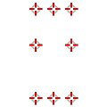
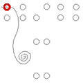
If a wire rope runs through more than two mounts, it is initially only fixed to the outer mounts (that is, grub screws are tightened); at the intermediate mounts, the cable is only inserted but the grub screws are not tightened. They can be lightly screwed in for temporary fixation of the rope so it does not slip out. The final tightening of these grub screws is done at the end or when, in the respective mount, a second rope is inserted a little later (photo). The mounts to be tightened are marked in bold red in the corresponding diagrams.
In places where wire ropes intersect, floating cross clamps are set (where indicated in the diagrams). At the end of assembly, protruding cable ends are bent behind the respective cable mount so that they constitute an extension of the wire rope axis. Fit the protective end sleeves (caps) onto the wire rope ends. If the wire ropes protrude about 10 cm, they can be easily grasped for re-tensionign in later years, as needed.