Special Case 02 for Installing Medium "Classic" Kits
The following installation instructions are only valid for some Medium Classic Kits. This section addresses kits that come with eyelet screws/eyebolts but no cross mounts. This applies to cable systems 6010, 7030, 7040 and 8020. All information here should be seen in connection with the 10 - 25 assembly diagrams for the respective cable system. Please use the link and follow it to the cable system you have ordered. The pictures shown here complete the diagrams there. Before ordering, please check to see if need tools!
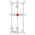
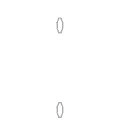
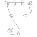
Each grey ellipse (in the diagrams) marks an eyebolt and shows its orientation according to the route of the cable. After drilling, clean all holes with a hole brush and/or blower. Then grasp the eyebolts at the flange nut and screw in using an open-end wrench. In the case of the WM 10080, this is done by means of a sturdy, transversely inserted screwdriver. At the points of the later rope loops (if necessary) insert thimbles and press together with a pair of pliers (photo).
The diagrams of the basic form show an installation requiring as little cutting as possible which also usually works without a turnbuckle (cable tensioner). For this purpose, the cable is initially pulled through several (or even all) eyebolts, in the order shown in each case. A double kink in the wire rope (photo) with 15 cm overhang facilitates the formation of the following, first loop.
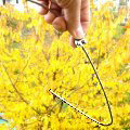
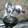
After threading the cable through the eyelets, form the first loop at the eyebolt indicated in the diagram. The cable must loop through the eyelet and fit into the grooves of the (pressed together!) thimble, clamped immediately behind it with a cable grip (clamp). Leave about 10 cm of extra cable behind the grip.

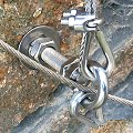
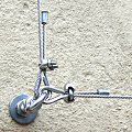
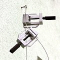
The next steps take place at the eyebolt through which the rope was first threaded. There, the end of the cable behind the eyelet is grasped by means of a mounting vice and pulled taut by hand (with about 5 kg force). Here, it is helpful to have a second mounting vice for securing both cable strands just behind the eyebolt (photo), so that the cable grip (diagram) can easily be set. Then the vices are loosened and the cable is cut-- with about 10 cm overhang -- behind the grip with a cable cutter.
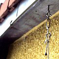
If a turnbuckle (cable tensioner) is used in the system (with a ground anchor or when installing long ropes in the roof area, for example), then the installation of one of the two cable loops takes place at one end of the turnbuckle. The loop will be hooked onto one of the hooks of the turnbuckel and the other hook of the turnbuckle will be hooked directly onto the eyebolt. A turnbuckle installed at ground level is easily accessible for later re-tensioning, while a turnbuckle positioned near the roof protects against potential vandalism and manipulation.

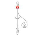
If the system includes additional cable segments (as indicated in diagram), they will be mounted according to the principle explained above. A floating cross clamp is placed at cable intersection points (diagram). Finally, all wire rope ends get pressed-on protective end sleeves (photo). With a 10 cm overhang of extra cable, you can easily re-tension them if they slacken over time.