Installation of Light Kits
Here we'll address the installation of Light Kits and of related self-assembled kits (with 6 mm-cross mounts and 1.5 mm cable). All information on this page should be supplemented in connection with the 10-25 mounting diagrams for each respective cable system. Please follow the link and go to the cable system you have purchased. (Follow the link to the cable system you have ordered; the pictures shown here complement the sequence graphics there.) The images shown here complement the diagrams. Before ordering, please check to see if you need tools!
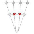
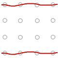
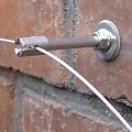
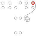
The symbols in the diagram represent the wire rope mounts. The little red bars indicate the alignment of the cross head grooves. After drilling, the holes should be cleaned out with a drill hole brush and air-pump blower. The cross mounts are inserted into the rawl plugs and fastened without grub screws (see photos). Please refer to the product sheet for the mount WM 06093. When mounting into exposed masonry, fastening into the joints is an option; in this case, then without the support washer.
With some systems, it is necessary to begin by cutting off one or more pieces of rope approx. 30 cm from the rope spool. These are loosely inserted into the grooves of the rope mounts (photo) without tightening the grub screws. The wire rope segment should protrude at least 5 cm on both sides behind each mount. Wavy red lines represent loose/slack wire rope. Further details can be found in the diagrams of the installation steps; wavy red lines respresent untensioned (slack) cables.
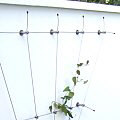
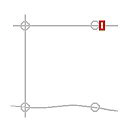
The diagrams of the respective basic forms show installations that require minimal cutting and that do not require a turnbuckle. Begin by laying the wire rope loosely into the first mount with a. 4 - 5 cm overhang. Then, insert the grub screws into the cross heads and fasten them by hand with an Allen key.
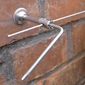
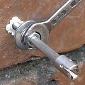
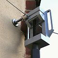
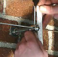
Then lead the cable to the next mount on the opposite side and place it into the groove. Grip the cable with a mounting vice directly behind the mount and tension by hand (medium manual force: 2-5 kg). A second mounting vice is particularly useful for the next step. It allows the two cables to be temporarily fixed direclty behind the cable grip in the tensioned position (see photo accompanying next paragraph). You then can insert and fasten the grub screw easily with both hands free. Proceed by cutting the wire rope behind the mount with wire cutters, leaving a 4 - 5 cm overhang.

For the assembly of some systems it will be necessary to tension a steel cable temporarily without inserting the grub screw, becasue a second cable has to be inserted into the other groove of the mount. A mounting vice clamping the cable directly behind the mount (see photo) will keep the cable in a taut position while the second cable is behind worked with, or with a wire rope stopper (clamping ring) or a cylindrical cross clamp which is often included in the cable system. After tightening the grub screws, you can remove the vice or cable clamp.
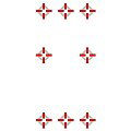
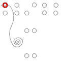
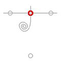
If a cable runs through more than two mounts, it should initially be secured only to the outer mounts (that is, tighten the grub screws of only the outer mounts). Leave the grubs screws of the intermediate mounts unscrewed, or screw them in only as a temporary fixation to prevent the cable from slipping out of the grooves. The final tightening of these grub screws happens at the end or when, in the respective mount, a second rope is fastened a little later (photo). In the diagrams, the mounts to be tightened are shown in bold red.
In places where wire ropes intersect, floating cross clamps are placed as the diagrams show. To finish, protruding cable ends are bent behind the respective cross mounts so that they represent an extension of the rope axis (so the entire cable is straight), and the cable ends are fitted with end sleeves. If the cables protrude about 4 - 5 cm, they can be easily gripped and re-tensioned in later years as needed.