Installation of Heavy Kits
Our wire rope trellises are available in five versions, from the simplest to the strongest. The heavy version is our second to last in the series. Here we'll cover the assembly of Heavy Kits, any of our systems in the heavy construction style, or for any self-assembled trellis using M12 mounts and 4 mm cable. All information on this page is to be used in connection with the 10 - 25 assembly diagrams that you can find on the page of your respective cable system. Please use the link and go to the cable system you have ordered. The images shown here supplement the diagrams there; they are also valid for the medium design construction (Medium Kits) when cross mounts but no eyebolts are included. Before ordering, please check to see if you need tools!
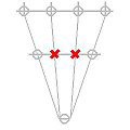
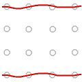
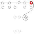
The symbols in the diagram represent the cross mounts; the red crosses show the alignment of the grooves of the screw head. After drilling, clean all holes with a brush and/or blower. Then install all wall mounts without the grub screws (photo). Consult the product data sheets of each trellis fitting/mount (for our heavy systems, the standard anchor is WM 12191, used together with SD 16130 sieve and VM 00300 composit mortar).
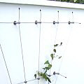
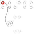
With some systems, it is necessary at the beginning to cut one or more pieces of wire rope with an excess length of 30 cm and loosely insert them into the grooves of the mounts (photo) without inserting or tightening the grub screws. On both sides, the wire rope should have a minimum of 10 cm overhang. Refer to the respective diagrams for further details. Slack ropes are represented by the wavy shape (diagram).
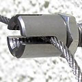
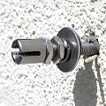
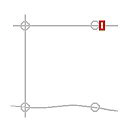
The basic-form assembly depicted here In the diagrams is one requiring as few cuts as possible and one which allows the cables to be tensioned without turbuckles. The first cable is laid slack in the first mount with about 10 cm overhang. The grub screw is inserted, moderately tightened, and in the second step, tightened again by holding the mount with an open-end wrench (see photo).
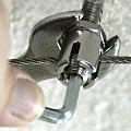
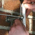
Then the wire rope is guided to the opposite mount and placed in the groove, gripped behind the mount with a mounting vice and pulled taut by hand (with about 10 - 20 kg force). It is often helpful to have a second mounting vice for temporary fixation directly behind the mount (photo one line below) so that inserting and tightening the grub screw is easier. Then -- again with about 10 cm of overhang -- cut the cable behind the mount with a cable cutter.

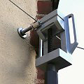
With some system shapes (arrangments), two cables cross each other perpendicular to the mount, such that you will have to wait until you have placed the second cable before securing the grub screw. For this reason, it is necessary to temporarily secure the first tensioned wire rope without screwing the grub screw into the cross mount. The cable is held in a taut position with a second mounting vice placed just behind the cable mount (see photo) or with a clamping ring or a cross clamp-- often included in the kit. After tightening the grub screw, remove the clamp.
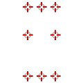
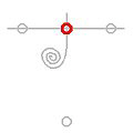
If a cable passes through more than two mounts, first tighten only the outer mounts. The grub screws of the intermediate mounts are only inserted; they are either not yet screwed in or only screwed in for temporary fixation of the rope so it does not slip out. The final tightening of these grub screws is done at the end of assembly or after the second cable has been inserted into the mount (see photo). The mounts to be tightened are shown in bold red in the diagrams.
At places where wire ropes intersect, place a free-floating cross clamp (when diagrams indicate). Bend the protruding cable ends (behind the mounts) in such a way that they represent an extension of the cable axis (i.e. that the cable appears to form a straight line). Finally, place a protective end sleeve on each cable end and press with pliers to secure. Let the cables protrude about 10 cm each so they can be easily grasped for ren-tensioning should they slacken in later years.