There are several options for attaching climbing aids to thermal insulation; spacer systems with supporting bodies (anchors) are one way. The mounting is then carried out in the finished plastered insulation, usually with composite mortar. Alternatively of course, a "preliminary" mounting is possible; see below. This page explains the assembly of such spacer systems and complements the product sheets of WM 12XX8 (for wire rope) and AS 12XX8 (for wooden trellises).
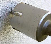
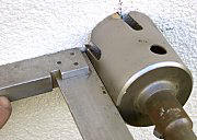
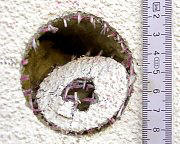
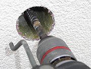
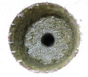
Aufbohren der Dämmung
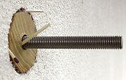
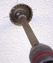
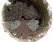
Beginners and DIY enthusiasts: please note the information about drilling. Insulation is to be cut with a cylindrical saw or similar (d = 60 mm bit), and dust and dirt vacuumed off. Use a hammer drill bit or percussion drill bit with 16 mm diameter for the central inner bore. Clean the base of the load-bearing wall of insulation residues, glue, bumps, etc. and smooth out, so that the spacer body of the wall mount gets a smooth, pressure-resistant contact surface. Smooth out larger irregularities with composite mortar, (if necessary) by inserting and turning a supporting body, preferably during the gluing of the mount/holder.
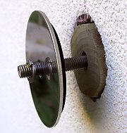
Setting the Distance Length
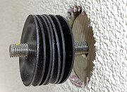
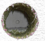
The wall mount is supported by a modular spacer block, which is assembled on site from the actual spacer (hardwood) distance block (hardwood or plastic) and a certain number of the corresponding (plastic) shims together. This requires a precise alignment. You may require no shims/spacers or up to 8 or 12, depending on the hole (photos). If thick spacers (shims) of 10 mm are used, these should be located directly behind the main spacer, and only then may 1.5 mm washers (regardless how many) follow when needed. In the case of variable surface/sublayers behind the insulation (refurbished old buildings), the alignment/adjustment may have to be made for each individual mount. If the substrate/surface is even, the alignment with one hole is completed and the determined composition/structure of the spacer block is then transferred to all other drill holes. In any case, the spacer block is assembled such that it protrudes 2-3 mm beyond the outer edge of the wall. In this way, the initially 5 mm thick wall seal is compressed during assembly without the EWIS/ETICS being deformed. The threaded shaft of the holder is put into the hole with the attached discs again and again until the correct number of shims is reached and the spacer block is optimally put together. If the spacer block is protruding less than 2 mm above the insulation surface, a concave deformation of the large stainless steel cover plate may occur while tightening the lock nut. With the subsequent/later insulating of old buildings, it happens that the insulation, due to irregularities in the wall, comes forward further than expected and the supplied support block is not long enough. After consultation with FassadenGrün, additional spacers or shims will be provided in this case.
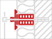
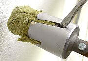
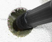
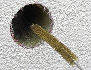
Assembly of the internal components
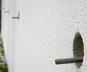
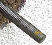
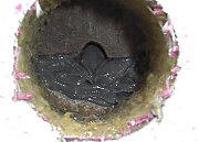
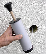
Incorporating threaded shaft and spacer block is usually done using composite mortar and sometimes also sieve sleeves (e.g. in hollow bricks etc.); both are described here. The assembly is shown in the photos here for a wall with mineral wool insulation. The photos are from different drill holes and clarify specific problem cases. With Styrofoam insulation, for example, the procedure is the same. The wall mount will be completely dismantled or has already been delivered that way. The drill diameter is shaft diameter plus 2-4 mm, an annular gap/ring gap of 2 mm thickness is better than one of only 1 mm, because the resulting thermal bridge (heat bridge) is reduced due to the low thermal conductivity layer of the mortar. When using mesh sleeves, always drill to 16 mm. Brush and blow out the boreholes multiple times. Then all threaded shafts are plugged into their holes...but first tentatively, checking to see whether they stick deep enough and are vertically and horizontally aligned. If this is not yet the case, drill again, shorten or bend shafts if necessary. With kinked threaded rods, it is best to mark a dot at the top with a grease pencil/wax crayon (yellow in the photo), which later makes it easier to insert correctly, thus ensuring a proper bonding. When bonding/adhering, one should proceed according to the instruction sheets of the composite mortar. The drill holes and sieve/mesh sleeves are sufficiently well filled with mortar, so that emerging composite mortar can be used as single-mass for the hardwood body simultaneously. For ledges and corners, in the area around the inner hole, there additional composite mortar is applied as 'adhesive'-- thus the hardwood body is sufficiently embedded and later completely secured. Then the threaded shafts and supporting bodies are glued. If several supporting bodies are installed (for example, 8 + 4 cm), insert the longer first. The loaded supporting bodies are pressed firmly against the load-bearing interior wall and facilitate the locking of the threaded rods; if necessary, additional aids, such as matches or toothpicks, can be used. After inserting a threaded shaft into the borehole which has been drilled with composite mortar, the shaft should have the chosen projection/overhand (5 - 8 cm, depending on the insulation thickness) over the outer wall and be aligned vertically and horizontally. A later correction of the insertion depth after the setting/hardening of the mortar is not possible-- bending or controlled/moderate blows can create minor self-adjustments. The rear support body is quasi bonded at the inner load-bearing wall. If the full load carrying capacity of the shaft is achieved according to the setting time indicated on the mortar cartridge, the further assembly takes place.
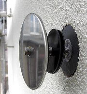
Installation of external components
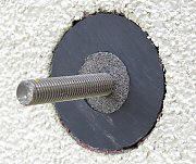
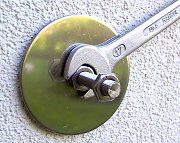
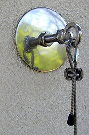
The shims are now placed as described above under 'Setting the distance length.' Then the stainless steel cover plate is placed on with the laminated sealing ring in the direction of the plaster. The spring washer and the two threaded nuts follow-- one as a clamping nut and the other as a lock nut for a crosshead (Phillips) or an eyelet/grommet. To reverse the crosshead, unscrew its Allen screw and insert a flat tool through one of the grooves to secure. Finally, with all holders -- also with variations where the holders were not disassembled -- the thrust nut, using the wrench, is tightened until a further rotation at a relatively high hand force is not possible, and the entire holder is tight. If necessary, fix the head against re-twisting with a second open-end wrench or the like (if it has been mounted with detachable threaded dowels). Only through this powerful clamping/tensing is the element at its capacity. The rest of the assembly is the same as described for Heavy Kits.