



Installation in ETICS before the insulation panels are installed
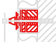
When installing a trellis on a facade where an ETICS external insulation system will be constructed, the steel mount is supported by a cellular glass cylinder glued to the masonry. The cylinder is delivered ready to use in the specified length chosen in accordance with the thickness of the insulation panels. Spacer disks made of plastic allow precise adjustment of the cylinder length and the evening out of uneven walls. All parts are installed before the ETICS panels are installed. We provide you here with step-by-step instruction for the "Before" installation procedure. The product sheets for the steel mounts XP 12XX3 and XP 12XX5 should also be read before proceeding. We recommend installing only ONE mount at first to familiarise yourself with the process and to adapt to local conditions.
Prerequisites
The insulation panels must be at least 12 cm thick without the coating. The material of the insulation must be rigid panels (polystyrene, EPS hard foam, mineral wool). There must be a solid supporting facade underneath: concrete, full masonry, hollow masonry, natural stone or cellular concrete.
Necessary Tools
You will need a Ø 95 mm (XP 12XX3) or Ø 127 mm (XP 12XX5) holesaw / cylinder saw, a Ø 16 mm hammer drill or, for insulation panels thicker 16 cm, an extra long hammer drill or a long percussion drill, and about 1/2 cartridge of compound mortar per cable mount together with an injection gun. For insulation panels > 16 cm, a mixing-tube extension is required. A motorized injection gun can facilitate the insallation (not available at FassadenGrün).
Other Tools
A laser is useful for marking the drilling points. Instead of a laser, a mason's wire (plumb bob cord) and a laser spirit level can be used to quickly mark the corner points. You will also need a folding rule / tape measure and two 19 mm open-end wrenches, a small piece of squared lumber or similar, a putty knife and painter's crepe (tape). An angle and a mini spirit level can help align the drill. A Ø 16 mm drill hole brush and a blower (or a compressor / compressed air) are needed to clean your drill holes; a vacuum cleaner to remove the drilling dust is also recommended. Additional tools -- a rope cutter/cable shears and 1 - 2 mounting vices -- will be very useful for attching the steel cables.
![[Translate to Englisch:] Fertig montierter Stützblock von XP 12XX3](/fileadmin/uw/rankhilfen/uw/artikel/xp12xx3/2100314-vorab-montage-a180.jpg "[Translate to Englisch:] Fertig montierter Stützblock von XP 12XX3")
01. Marking und Alignment
Beginners and do-it-yourselfers: please consult our info sheet on drilling operations before proceeding! Mark the drilling point and place the cylinder saw at the marked location. Then adjust the position of the drill bit with a spirit level and/or an angle; proceed with drilling. Check the alignment of the drill in all directions while drilling!


03. Drilling
Adjust the position of the Ø 16 mm drill with a spirit level and/or a stop bracket (back square). Then drill. If using chemical mortar sieve sleeves, drill 14 cm deep; otherwise, drill to the anchoring depth (the depth at which the fitting witll be driven into the facade, so approx. 9 - 12 cm) + 1 cm.


05. Einstecken der Siebhülse
Die Hohlform und das hintere Bohrloch sind auszubürsten, auszublasen und abzusaugen, am besten mehrfach. Falls hinten Hohlmauerwerk ansteht, wird jetzt zunächst die Siebhülse gesteckt. Bei Vollmauerwerk entfällt dieser Schritt. Der Stützkörper samt Gewindestange ("Korpus") kann nun probehalber schon einmal gesteckt werden.

06. Loch bzw. Siebhülse mit Mörtel füllen
Jetzt bitte die Bauanleitung des Verbundmörtels beachten (anfänglicher Null-Strang, Temperaturen, Offenzeiten, Aushärtezeiten). Ggf. Mischrohr-Verlängerung nutzen. Die Kartusche sollte mindestens halb voll sein, um Unterbrechungen zu vermeiden. Wichtig: Hinten im Bohrloch ansetzen, Mischrohr langsam herausziehen. Dann sofort zu Schritt 07 gehen.

07. Stützkörper vorbereiten
Es wird geprüft, ob die Verbundmörtel-Kartusche noch genügend Mörtel enthält (ca. 1/4 Kartusche), um jetzt ohne Unterbrechung arbeiten zu können. Dann die beiden Transportsicherungen des Korpus entfernen und wenn möglich bitte (nebst Leihwerkzeug) an FassadenGrün zurück senden. Anschließend wird Verbundmörtel sehr dick, als spiralförmige "Raupe" auf der Rückseite des Korpus auftgetragen. Im Ausnahmefall - wenn der Luftspalt zwischen Dämmung und tragender Wand größer als erwartet war - wird die Vorderseite verklebt.

08. Stützkörper mit Schaft einsetzen
Der "Korpus" samt Gewindestange wird zum Verkleben an die Wand gedrückt, am besten "leicht DREHEND", damit der Mörtel sich gut verteilen und dem Untergrund anpassen kann. Wenn der Korpus außen annähernd bündig mit der Dämmplatte abschließt, entfallen die Schritte 09 und 10!

09. Distanzscheiben Kunststoff
Dieser Schritt ist eventuell nicht nötig - siehe bei Schritt 08! Es werden jetzt so viele Distanzscheiben aus Kunststoff h=5 mm aufgesteckt, dass noch ca. 3 - 5 mm Abstand zur Außenkante der Dämmschicht bleiben. Nicht benötigte Scheiben werden von FassadenGrün zurück genommen!

10. Stützblock verspannen
Dieser Schritt ist eventuell nicht nötig - siehe bei Schritt 08! Die Sechskant-Flachmutter und die Edelstahlscheibe d=50 mm werden aufgesteckt und fest angezogen, der gesamte Stütz-Block wird dadurch verspannt und stabilisiert. Zum Überstand der Flachmutter siehe nächste Grafik.

11. Überstand der Mutter prüfen
Je nach Art des geplantes Putzes (Dünnschicht- oder Dickschicht) darf die Flachmutter - falls sie montiert wurde - maximal 2 mm oder 6 mm aus der Dämmschicht hervorstehen. Sie muss unter dem künftigen Putz verschwinden. Ggf. wird die Anzahl der Ausgleichsscheiben nochmals verändert.


16. Weitere Muttern
Anschließend werden Langmutter und Flachmutter (XP 12XX5) bzw. zwei Flachmuttern (XP 12XX3) aufgeschraubt. Eine Mutter wird als Kontermutter gegen die Kegelmutter angezogen, dazu wird ein zweiter Maul- oder Ringschlüssel benutzt. Die letzte Flachmutter verbleibt weiter außen am Gewindeschaft.


18. Montage des Halter-Kopfes
Dann wird der Kopf ohne Madenschraube aufgeschraubt und mit der Flachmutter als Kontermutter justiert. Dabei wird ein flaches Werkzeug (Schraubendreher) zum Gegenhalten durch eine der Nuten des Kopfes gesteckt. Die weitere Montage erfolgt dann nach den Vorgaben des jeweiligen Seilsystems bzw. so wie für schwere Bausätze beschrieben.
